
Published by HydroGeo Envi-Consultancy Services. Content updated .
Quick answer
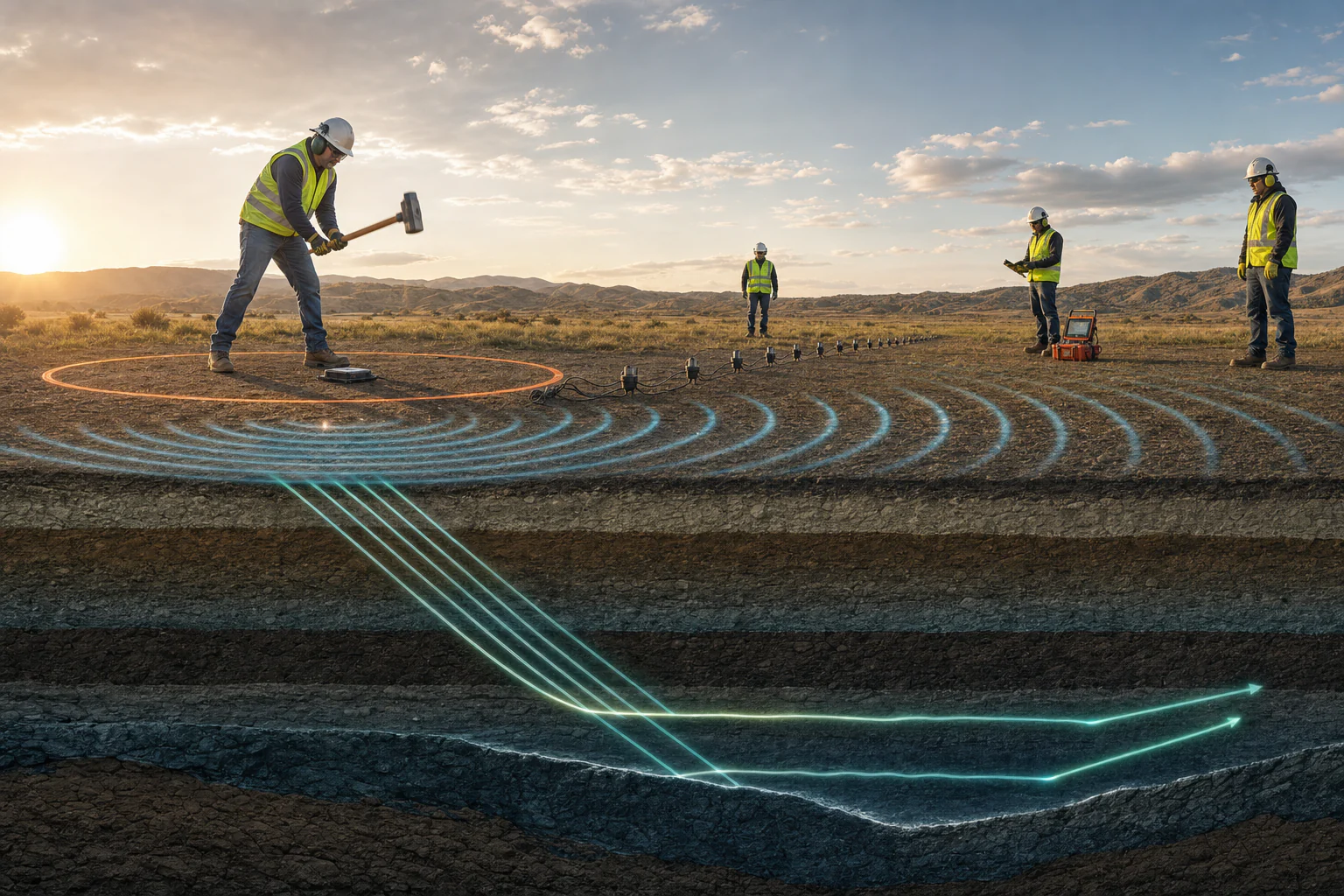
MASW and seismic refraction can use similar field equipment and sometimes the same records, but they analyze different wave behavior. MASW studies the dispersion of surface waves to estimate shear-wave velocity structure. Seismic refraction analyzes first-arrival travel times to estimate compressional-wave velocity structure and refracting interfaces or gradients. Their outputs are complementary, not interchangeable, and neither alone confirms geology or final geotechnical design parameters.
What the topic means
Multichannel analysis of surface waves, or MASW, evaluates how surface-wave phase velocity changes with frequency or wavelength. A dispersion curve is selected and inverted into one-dimensional profiles or two-dimensional images of shear-wave velocity, subject to mode selection and model assumptions. Refraction work identifies first arrivals from seismic records, builds travel-time curves, and uses layered or tomographic modeling to estimate compressional-wave velocity and raypath-supported structure.
When it may be relevant
- Screening stiffness or weathering variation through shear-wave or compressional-wave velocity.
- Supporting ground-model development between boreholes or exposures.
- Investigating possible low-velocity, weathered, fractured, fill, rockhead, or lateral-transition contexts.
- Providing method-specific evidence for later geotechnical site classification or design review by the appointed professional.
Useful information and inputs
- The required decision, target depth and resolution, line access, topography, and expected velocity structure.
- Source type and offsets, receiver spacing and spread length, channel order, sensor type, sampling interval, record length, and trigger timing.
- Coordinates, elevations, line direction, coupling conditions, ambient and cultural noise, and field observer notes.
- Boreholes, geology, laboratory or in-situ tests, groundwater, and previous geophysical data for correlation.
- The adopted analysis purpose, including whether later site classification or design criteria must be addressed separately.
How the method or assessment generally works
Field records are checked for geometry, timing, channel order, clipping, dead or noisy traces, coupling, source consistency, and usable offsets. For refraction, first arrivals are picked with uncertainty, plotted as travel times, and modeled with documented starting conditions, regularization, topography, residual definition, ray coverage, and alternatives. For MASW, the records are transformed to frequency-velocity or wavelength-velocity images; usable modes are picked, then inverted with stated bounds, layering, assumptions, fit, sensitivity, and alternative models.
The two results are compared only after their different physics, coverage, resolution, and depth sensitivity are made explicit.
Typical outputs
- Survey geometry, record-quality, source, receiver, and exclusion register.
- Representative seismic gathers and first-arrival pick overlays.
- Travel-time plots, refraction velocity model, residuals, and ray-coverage display.
- Dispersion images, mode picks, observed-versus-modeled curves, and shear-wave velocity profiles or sections.
- Method comparison, uncertainty, correlation, and confirmation notes.
How the outputs should be interpreted
Compressional-wave and shear-wave velocities respond differently to material, stress, porosity, saturation, fractures, and structure. A velocity boundary is not automatically a lithologic contact. A smooth MASW profile does not prove unique layering, and a refraction model may have limited ability to resolve a lower-velocity layer beneath a higher-velocity layer. Empirical correlations can support screening only within their evidence and validity; they are not laboratory measurements.
QA/QC and evidence checks
- Verify source-receiver geometry, stationing, line direction, coordinates, elevations, units, timing, sensor response, and acquisition completeness.
- Retain first-arrival picks with uncertainty and review reciprocal or repeat behavior where available.
- For MASW, check spatial aliasing, usable wavelength range, near and far offsets, mode selection, mode crossings, fit, sensitivity, and non-unique alternatives.
- For refraction, check ray coverage, topography, residual structure, hidden low-velocity alternatives, and dependence on the starting model or constraints.
- Cross-check every velocity, depth, frequency, wavelength, mode, line and unit among figures, tables, and narrative.
Limitations and common misunderstandings
Depth of investigation is not a fixed generic fraction that applies to every survey; it depends on array, source, frequency or wavelength content, data quality, model, and acceptance criteria. Good curve fit or small travel-time residuals do not demonstrate a unique ground model. Combining methods can reduce uncertainty only when their independent limitations and spatial references are preserved.
What may be needed for confirmation
Confirmation may include boreholes, SPT or CPT, downhole or crosshole testing, test pits, core logging, density and laboratory tests, groundwater observations, geological mapping, or exposure logging. Final engineering parameter adoption, seismic site classification, foundation assessment, slope analysis, and design decisions require the applicable criteria and qualified geotechnical review.
What to prepare before contacting HydroGeo
- The decision, desired depth and resolution, project stage, and expected ground conditions.
- A plan showing proposed lines, access, slopes, traffic, buried services, vibration restrictions, and noise sources.
- Existing borehole, laboratory, geological, groundwater, structural, and design information.
- Any required output format or downstream geotechnical review interface.
Project-planning reference
Evidence table and decision graph
Use these source-derived summaries to organize an enquiry and identify useful records. They are general guidance, not project data or a substitute for site-specific professional review.
MASW and seismic-refraction evidence comparison
| Feature | MASW | Seismic refraction | Interpretive control |
|---|---|---|---|
| Primary signal | Dispersive surface-wave energy | First-arriving refracted body waves | Acquisition and processing must preserve the relevant arrivals |
| Main output | Shear-wave velocity structure inferred from dispersion | Compressional-wave velocity structure inferred from travel times | Velocity is a physical property, not a material name |
| Depth control | Frequency content, array length, mode identification and inversion | Source–receiver geometry, velocity contrasts, layer geometry and first-arrival quality | Depth and resolution vary with site and survey design |
| Typical integration | Dynamic site characterization and stiffness context | Layering, rockhead/weathering and velocity-boundary context | Combine with boreholes, geology and geotechnical evidence |
| Important ambiguity | Mode selection and non-unique inversion | Hidden or velocity-reversal layers and non-unique geometry | Alternative models and sensitivity should remain visible |
On a small screen, swipe the table sideways to review every column.
Source-derived relationship
Different wave paths lead to different velocity models
A four-stage comparison from recorded wavefield through surface-wave or first-arrival analysis to velocity models and integrated interpretation.
- Recorded wavefieldSource, receivers, geometry, timing and noise
- Signal pathwayDispersion image for MASW or first arrivals for refraction
- Velocity modelShear-wave velocity or compressional-wave velocity
- Integrated useCompared with geology, boreholes and the project decision
Source basis and use boundary
This comparison does not select MASW, refraction, an array, source, processing method or design parameter. The target property and site conditions control suitability.
- USGS — Multichannel Analysis of Surface Waves—Active and Passive MethodsSurface-wave acquisition and analysis, active and passive approaches, dispersion, and shear-wave-velocity characterization.
- FHWA — Geotechnical Site Characterization (FHWA-NHI-16-072)Planning and combining borings, in-situ tests, laboratory testing, groundwater observations, geophysics, parameters, and subsurface models.
Primary sources reviewed 2 September 2026. Recheck the linked source and applicable project criteria before relying on current requirements.