
Published by HydroGeo Envi-Consultancy Services. Content updated .
Quick answer
A drainage or flood assessment needs more than a project boundary and one rainfall value. The minimum defensible inputs depend on the decision, but typically include reliable terrain, catchment and flow-path information, rainfall or flow data, existing and proposed drainage geometry, downstream and boundary conditions, land cover and soil context, observed flooding, adopted design criteria, and the project grading or development concept. Missing inputs should be exposed through sensitivity cases rather than hidden behind default values.
What the topic means
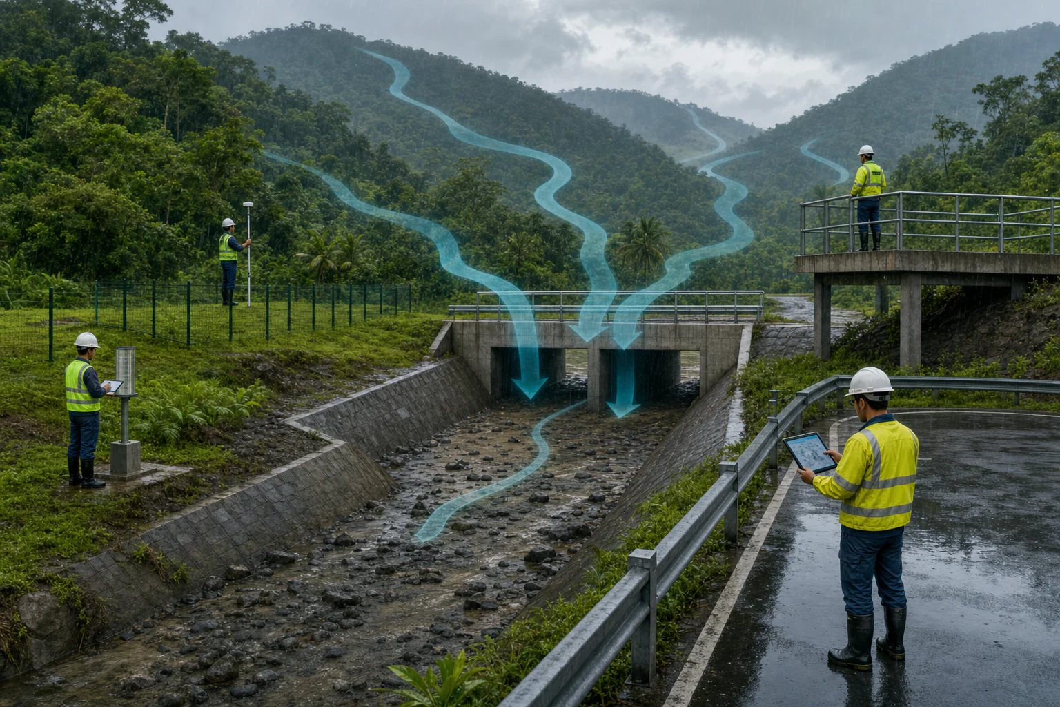
Hydrologic assessment estimates how rainfall becomes runoff and how that runoff moves through, across, or around a project. Hydraulic assessment evaluates water levels, depth, velocity, conveyance, storage, structures, and floodplain behavior. Drainage assessment may combine both, from local inlets and pipes to channels, culverts, detention facilities, outfalls, and receiving waters. The method should match the scale and the decision rather than beginning with a preferred software package.
When it may be relevant
- Site development, subdivision, road, industrial, detention, channel, culvert, bridge, or stormwater planning.
- Observed ponding, overtopping, erosion, scour, backwater, blocked drainage, or downstream complaints.
- Review of pre-development and post-development runoff, proposed grading, storage, or discharge controls.
- Flood screening that must be advanced into a project-specific hydrologic or hydraulic assessment.
Useful information and inputs
- Project boundary, current and proposed grading, impervious areas, construction stages, and drainage concept.
- Terrain or survey with horizontal and vertical reference, drainage breaklines, channels, roads, embankments, walls, and low points.
- Catchment boundaries, land cover, soils or infiltration context, existing drainage network, culverts, outfalls, and storage areas.
- Official rainfall intensity-duration-frequency data, temporal distribution, observed rainfall and flow or water-level records where available.
- Downstream water levels, tidal or river boundaries, blockage or debris context, and documented flood marks or event photographs.
- Adopted return periods, freeboard, allowable discharge, climate or change scenarios, and other project or authority criteria.
How the method or assessment generally works
The assessment defines the outlet and decision area, checks terrain and drainage connectivity, delineates catchments, and establishes current and proposed scenarios. Rainfall is converted to runoff using a method suited to the catchment, event, data, and project stage. Where flow routing, channels, structures, or inundation are important, a hydraulic representation is developed with documented geometry, roughness, losses, structures, initial and boundary conditions, and computation settings.
Observed events should be used for calibration or reasonableness checks where suitable data exist. If calibration data are unavailable, the model should be described as unvalidated and tested across plausible ranges for rainfall, losses, roughness, blockage, inflow, boundary levels, geometry, and drainage condition.
Typical outputs
- Catchment, subcatchment, drainage-path, and outfall maps.
- Rainfall assumptions, runoff estimates, and hydrographs.
- Drainage or structure capacity summaries and controlling-condition notes.
- Water-level, depth, velocity, or inundation outputs where hydraulic modeling is justified.
- Scenario comparison, data-gap, uncertainty, and follow-up-action register.
How the outputs should be interpreted
A modeled flood outline is a scenario result, not a survey of where water will stop in every future event. Cell size, terrain accuracy, building and wall representation, drainage blockage, rainfall pattern, downstream level, and model assumptions affect the result. A calculated capacity does not prove performance if the asset geometry, condition, inlet control, tailwater, debris, maintenance, or connected system is not represented accurately.
QA/QC and evidence checks
- Reconcile project, survey, terrain, model, and map coordinate systems and vertical datums.
- Check catchment area and connectivity against terrain, site observation, and known drainage structures.
- Trace rainfall source, station, record length, duration, return period, temporal pattern, and adopted climate basis.
- Review missing data, parameter provenance, mass balance, time-step stability, boundary placement, and warnings.
- Compare modeled behavior with flood marks, photographs, reports, flow or level records, and independent hand checks where available.
Limitations and common misunderstandings
A short site visit cannot replace event data, and a large regional DEM may not represent local kerbs, walls, drains, culverts, or floor levels. Published default parameters are not calibrated site values. One design storm does not cover every duration, antecedent condition, boundary level, blockage, failure, or construction stage. Hazard mapping, capacity checking, and detailed drainage design are different levels of work.
What may be needed for confirmation
Confirmation may require detailed survey, culvert or pipe inspection, invert and outfall levels, channel cross-sections, flow or water-level monitoring, rainfall records, infiltration testing, condition assessment, CCTV, observed-event calibration, and field verification of drainage connectivity. Detailed design also requires the adopted criteria and review authority for the specific project.
What to prepare before contacting HydroGeo
- Project boundary, grading or layout, current drainage concept, and the decision or approval stage.
- Available survey, terrain, drainage drawings, structure schedules, rainfall or flood records, and previous studies.
- Observed ponding, overtopping, erosion, blockage, or downstream issues with dates and photographs.
- Known design criteria, receiving-water constraints, planned phases, and access limitations.
Project-planning reference
Evidence table and decision graph
Use these source-derived summaries to organize an enquiry and identify useful records. They are general guidance, not project data or a substitute for site-specific professional review.
Input-to-decision map for drainage and flood work
| Input family | Role in the assessment | QA/QC question | Risk if weak or missing |
|---|---|---|---|
| Terrain and survey | Defines slopes, storage, flow paths, channels and low points | Are datum, resolution, channel and structure elevations suitable? | Water may be routed or mapped in the wrong place |
| Rainfall and event basis | Defines the forcing applied to the catchment | Are duration, temporal pattern, frequency basis and climate assumptions stated? | Runoff magnitude and timing become unsupported |
| Catchment and losses | Controls contributing area and conversion of rainfall to excess runoff | Are land cover, soil, infiltration and antecedent assumptions traceable? | Runoff volume may be misrepresented |
| Drainage geometry | Represents channels, pipes, culverts, inlets, crossings and obstructions | Were dimensions, invert levels, condition and connectivity verified? | Capacity and bottleneck conclusions may be wrong |
| Flow and boundary conditions | Controls upstream inflow, downstream stage and system response | Do boundaries cover the modeled event and avoid influencing the area of interest? | Depth, velocity and extent can be distorted |
On a small screen, swipe the table sideways to review every column.
Source-derived relationship
Hydrology-to-hydraulics evidence chain
A four-stage graph from rainfall and catchment evidence through runoff transformation, hydraulic representation, and decision outputs.
- Rainfall + catchmentEvent basis, area, land cover, soil and losses
- Runoff hydrographExcess rainfall transformed and routed
- Hydraulic systemTerrain, channels, drainage assets, roughness and boundaries
- Decision outputsCapacity, depth, extent, velocity, bottlenecks and sensitivities
Source basis and use boundary
The workflow does not select a design event, rainfall dataset, loss method, roughness value or boundary condition for a particular project; those choices require the applicable criteria and verified site data.
- USACE — HEC-HMS DocumentationWatershed representation, precipitation, losses, excess-runoff transformation, baseflow, routing, and hydrologic outputs.
- USACE — HEC-RAS DocumentationTerrain and geometry, roughness, structures, flow and boundary conditions, hydraulic computation, and inundation review.
Primary sources reviewed 2 September 2026. Recheck the linked source and applicable project criteria before relying on current requirements.