
Quick answer
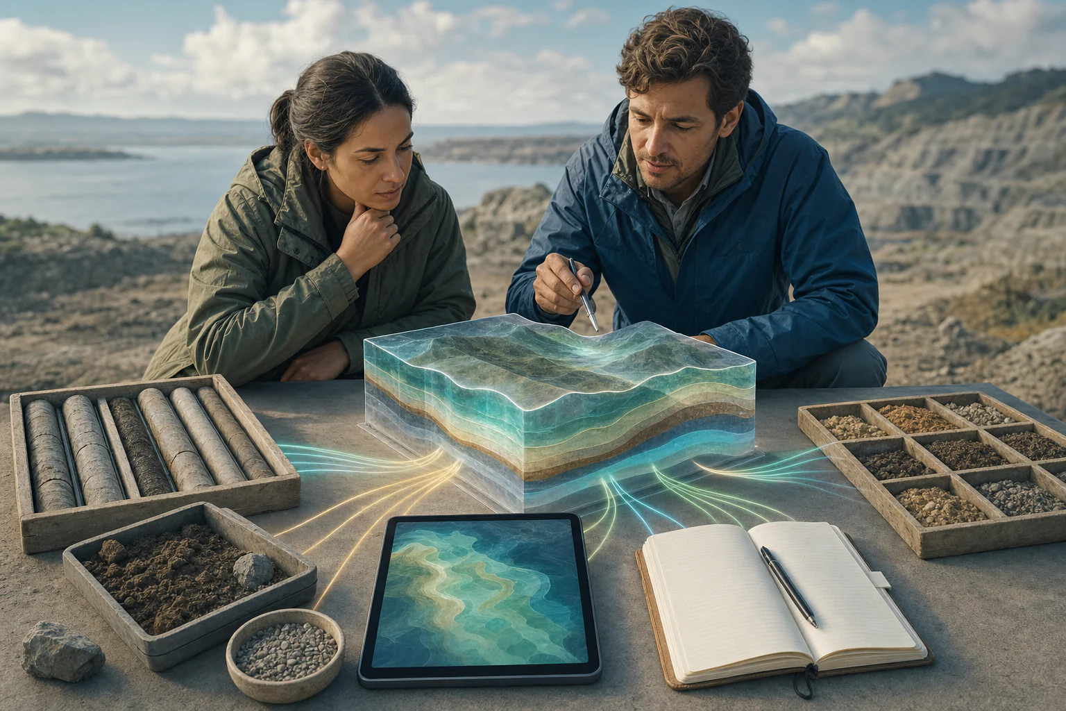
A geotechnical ground model is a decision-focused representation of the ground, groundwater, and relevant geological structures beneath a site. It does not simply connect borehole logs. A defensible model reconciles mapping, terrain, boreholes, test pits, samples, in-situ tests, laboratory results, geophysics, groundwater observations, construction history, and proposed works while showing where conditions are observed, interpreted, uncertain, or unsupported.
What the topic means
The model organizes available evidence into geological units and, where appropriate, separate engineering units with behavior relevant to the project. It may be expressed as plans, sections, profiles, tables, or a three-dimensional framework. Because investigation points sample only part of a site, every ground model contains interpretation and simplification. Its value comes from traceability: users should be able to see what supports each contact, unit, parameter context, groundwater condition, and uncertainty.
When it may be relevant
- Planning foundations, slopes, excavations, roads, embankments, retaining systems, drainage, or ground improvement.
- Reconciling inconsistent borehole descriptions, laboratory results, geophysical models, or historical records.
- Identifying investigation gaps before detailed design or construction.
- Updating the project understanding when new drilling, exposure, monitoring, or construction evidence becomes available.
Useful information and inputs
- Project boundary, proposed structures and earthworks, design stage, and decisions to be supported.
- Topographic survey, coordinate reference system, vertical datum, terrain and drainage information.
- Borehole and test-pit logs, core photographs, sample records, SPT or CPT data, and laboratory results.
- Geological mapping, geomorphology, discontinuities, groundwater levels and dates, pumping or permeability tests, and geophysics.
- Historical land use, fill placement, previous structures, excavations, instability, flooding, or construction observations.
How the method or assessment generally works
Sources are first inventoried and placed in a common horizontal and vertical reference. Each observation retains its source, date, method, location, depth or elevation, quality, and limitation. The team defines correlation rules before drawing contacts between investigation points. Geological units describe origin, composition, weathering, structure, and continuity; engineering units group materials only when the available evidence supports similar project-relevant behavior.
Alternative models are retained when evidence supports more than one explanation. Groundwater conditions are time-dependent and should be tied to dates, rainfall, pumping, tide, construction, or other relevant states. The model is then tested against the proposed works and the failure mechanisms or performance questions that matter to the project.
Typical outputs
- Evidence register with stable source and investigation identifiers.
- Geological and engineering-unit descriptions with supporting observations.
- Plans, cross-sections, profiles, or fence diagrams distinguishing observed and inferred boundaries.
- Groundwater-state interpretation tied to observation dates and limitations.
- Uncertainty, alternative-model, design-dependency, and confirmation-action summaries.
How the outputs should be interpreted
A line drawn between boreholes is a correlation, not a direct observation. A geophysical boundary is a physical-property contrast, not automatically a geological contact. A laboratory result applies to the tested specimen and method; adopting a project parameter requires broader review of representativeness, variability, stress and drainage conditions, scale, and the design model. The ground model should therefore be read together with its evidence density, confidence, interpolation limits, alternatives, and revision status.
QA/QC and evidence checks
- Reconcile coordinates, elevation and depth references, units, investigation IDs, and dates.
- Preserve raw logs and measurements; document corrections, correlations, exclusions, and transformations.
- Compare written logs, photographs, recovery, sampling, field tests, laboratory results, and geophysics for agreement and conflict.
- Check that groundwater observations are not combined as though measured at the same time or under the same conditions.
- Show boreholes, exposures, and other controls on every decision-bearing section and mark unsupported interpolation or extrapolation.
Limitations and common misunderstandings
A detailed drawing is not evidence of detailed subsurface knowledge. Sparse data cannot confirm continuous layers or uniform properties. Geological units do not necessarily have uniform engineering behavior, and engineering units may cross geological names where behavior is the relevant grouping. A ground model supports analysis and investigation planning; it does not replace final design calculations, adopted criteria, or qualified professional review.
What may be needed for confirmation
Additional boreholes, CPTs, test pits, laboratory tests, geophysical lines, water-level monitoring, permeability testing, survey control, exposure mapping, or construction-stage observations may be needed. Confirmation should target the uncertainty that could change a design, sequence, quantity, safety control, or performance decision.
What to prepare before contacting HydroGeo
- The current project layout, anticipated loads or earthworks, and the decisions the model must support.
- All available investigation files in their original coordinate, depth, and unit conventions.
- Known changes in site grade, land use, drainage, groundwater, access, or construction staging.
- The required output scale, design interfaces, schedule, and identified evidence gaps.
Project-planning reference
Evidence table and decision graph
Use these source-derived summaries to organize an enquiry and identify useful records. They are general guidance, not project data or a substitute for site-specific professional review.
What each evidence family contributes to a ground model
| Evidence family | Primary contribution | Important control | Common overreach to avoid |
|---|---|---|---|
| Mapping and terrain | Landform, exposure, structure, drainage and surface continuity | Scale, date, datum and field verification | Extending surface conditions through the full subsurface |
| Borings and test pits | Direct descriptions, samples and point-specific contacts | Location, elevation, recovery, logging and disturbance | Drawing continuous layers from sparse points without uncertainty |
| In-situ and laboratory tests | Measured response or specimen properties under stated procedures | Test method, sample quality, stress/drainage state and representativeness | Treating one result as a universal design parameter |
| Geophysics | Between-point physical-property continuity and anomalies | Resolution, coverage, non-uniqueness and calibration | Naming materials solely from a physical-property contrast |
| Groundwater and monitoring | Time-dependent levels, pressures and change | Dates, rainfall, pumping, tide and construction state | Combining observations from different states as one surface |
On a small screen, swipe the table sideways to review every column.
Source-derived relationship
Evidence convergence into a traceable ground model
A four-stage graph showing source-controlled evidence, reference reconciliation, interpretation with alternatives, and decision-focused model use.
- Source evidenceLogs, samples, tests, mapping, survey and monitoring
- ReconciliationIDs, coordinates, elevation, depth, dates and units aligned
- Model alternativesObserved and inferred boundaries, units and uncertainty
- Decision modelRelevant mechanisms, gaps and confirmation actions
Source basis and use boundary
The graph does not convert investigation results into design parameters. Parameter selection and design models require project-specific representativeness, variability and qualified review.
- FHWA — Geotechnical Site Characterization (FHWA-NHI-16-072)Planning and combining borings, in-situ tests, laboratory testing, groundwater observations, geophysics, parameters, and subsurface models.
- FHWA — Subsurface Investigation GuidanceSelection, planning, QA/QC, interpretation, and reporting for in-situ, geophysical, and laboratory characterization methods.
Primary sources reviewed 2 September 2026. Recheck the linked source and applicable project criteria before relying on current requirements.